WARNING: Never enter, walk around on or let alone drive any vehicle on ANY active railway! Active railways are dangerous and not a playground. You can get hurt or killed. Always make sure to check if a railway line is actually "dead" and verify that there is no way a train can enter the track. Check your local laws before you do anything like this!
So I've had this idea in mind for a long time, and every time I came across some abandoned tracks in the forest or next to some abandoned building, I thought about it. A small kart to drive along these old lines would be awesome! But so much effort, and you're only going to use it a few times per year at best... But recently, I came across a particularily nice abandoned line and decided to finally make this thing a reality. Here are some images of the build process, along with descriptions of the process. Enjoy!
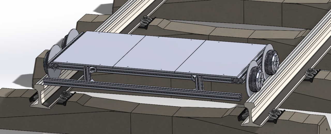
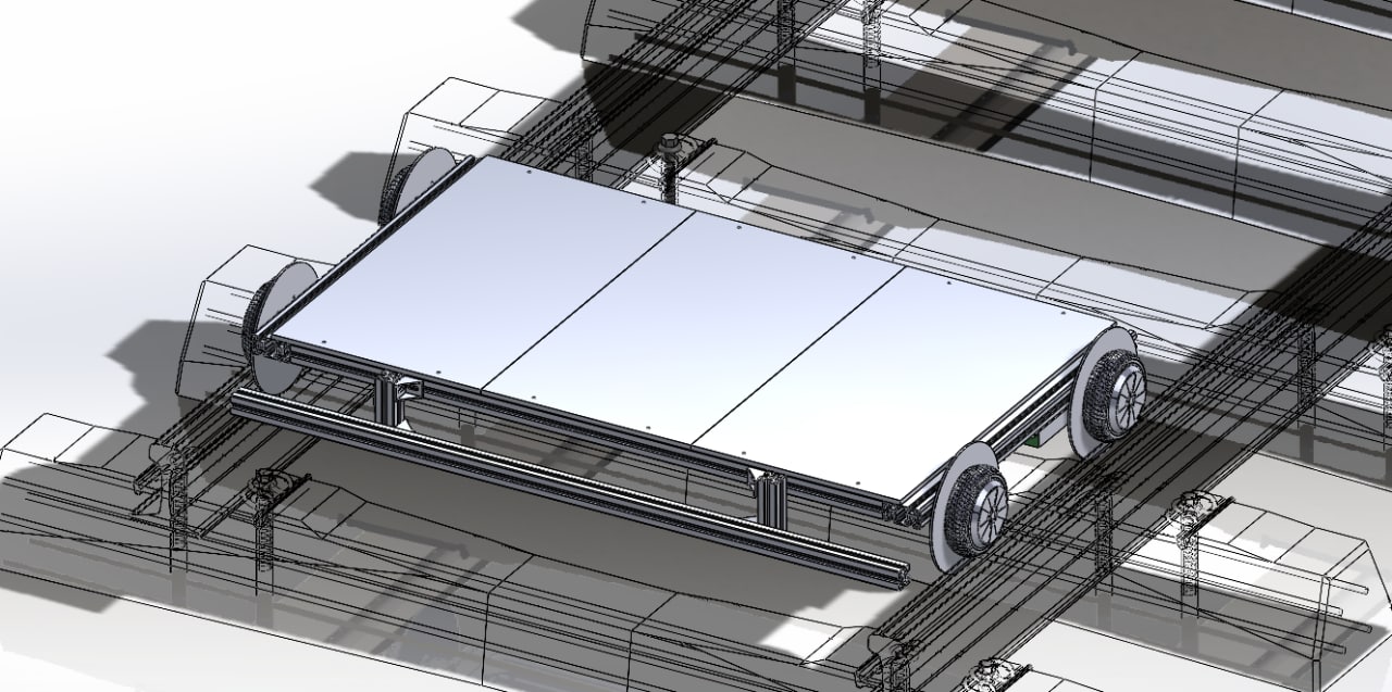
Before even touching a single screw, I fired up my CAD software, downloaded various 3D models of things like 1435 mm gauge rails, hoverboard wheels etc. and had a go. Over the course of a few days, I had a pretty simple, but solid design I was happy with:
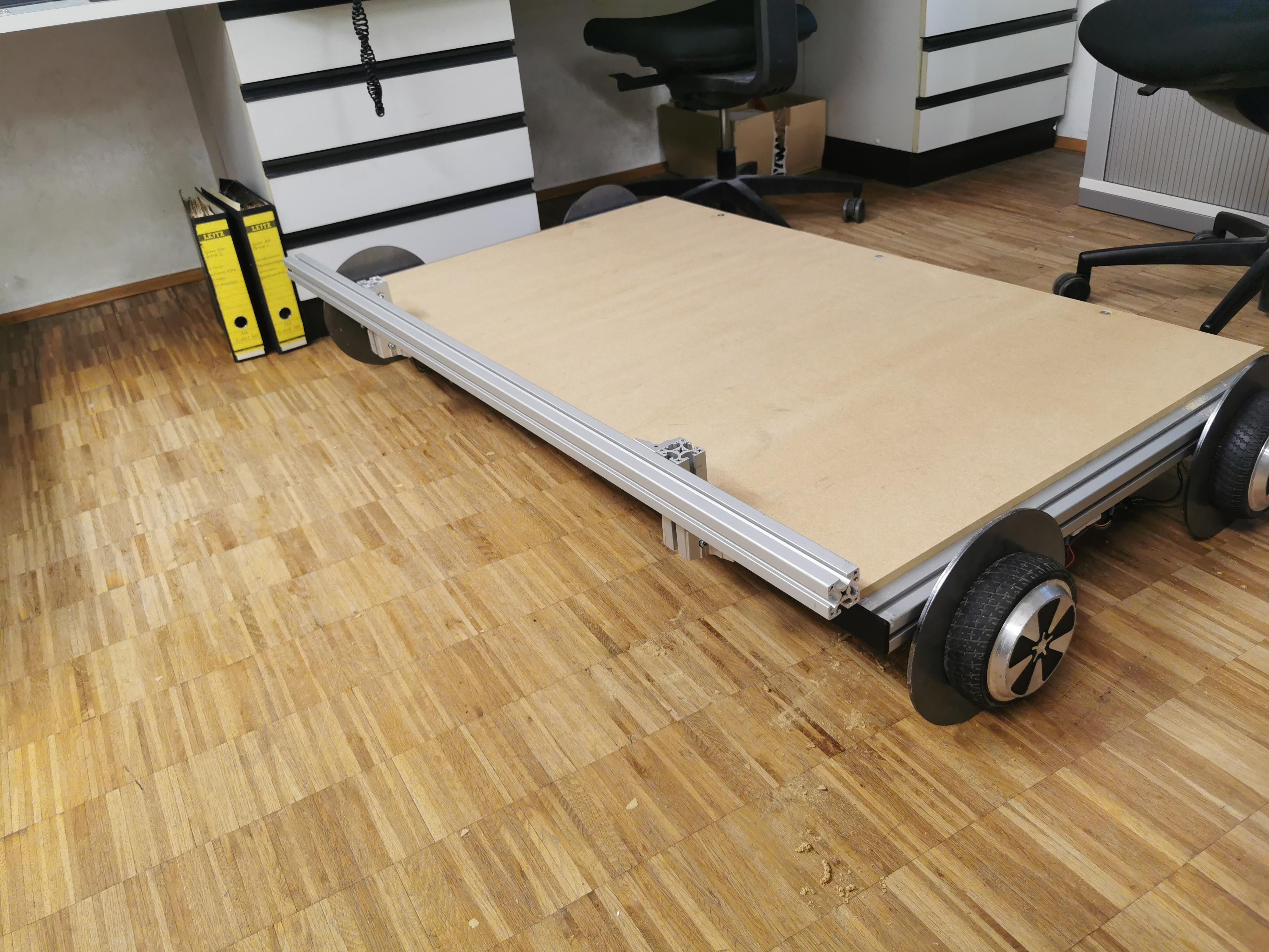
My main design goal was that the kart should be easy to (dis-)assemble and transport. Obviously, it was going to be very wide, since most track in my area is 1435 mm gauge. This would be hard to fit in a car, so I made it somewhat modular, with three separate wooden boards for seating and easy to remove aluminium extrusions. I also wanted it to carry two people, so I could go on Amazing Abandoned Adventures with friends. The first version of the kart looked a bit odd since it was really short, just 60 cm. After imagining myself sitting on it, I came to the conclusion that this wouldn't be comfortable.
After tweaking it to be 80 cm long instead, it felt right and also didn't look as strange anymore. So I got all the important measurements for the aluminium extrusions and forwarded them to Phalos, who got the extrusions for me and sawed them to the correct lenghts, so we could build the frame next time I visited him.
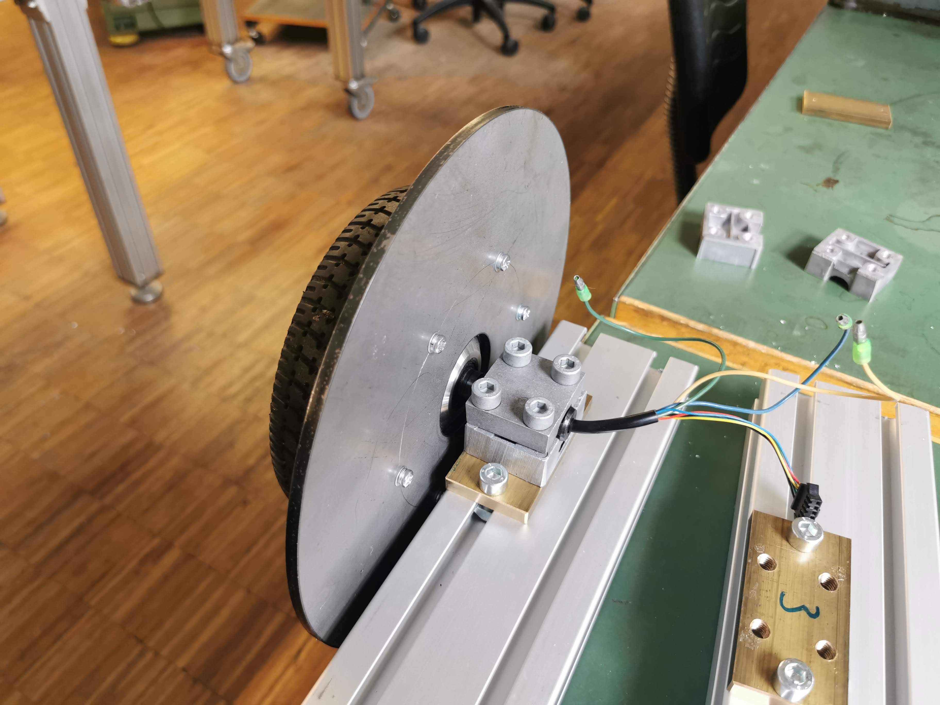
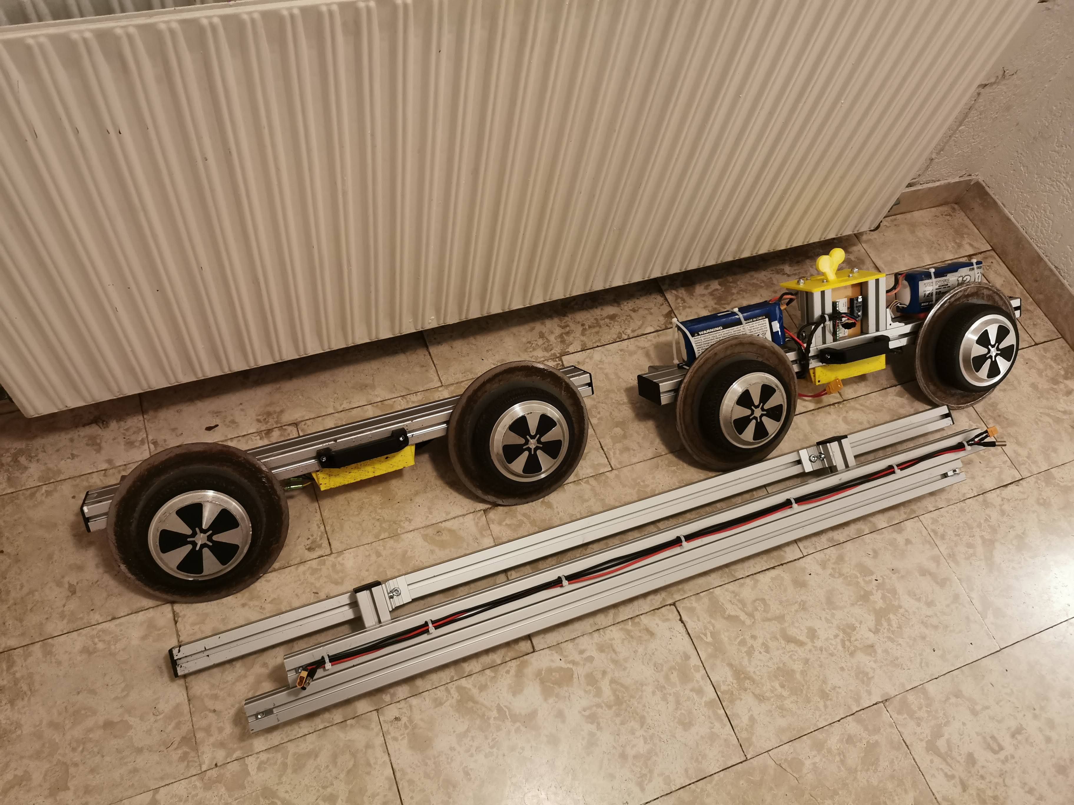
This was one thing I could already do at home. I had one working hoverboard laying around. That's two wheels, but I need four. So I bought another one cheaply for parts. I then gutted both hoverboards and took their motors and main control boards. To make a rail vehicle, you don't just need wheels. You also need a wheel flange to keep the wheels from rolling off the track to the sides. So I bought some steel disks to use as primitive wheel flanges. Normally, a rail wheel has a specific shape with a slight slope, which causes it to self-center on the track. Since I didn't want to go THAT far, I decided that just having the hoverboard's rubber wheels run on the track and adding the steel disks as a flange would be enough.


Here you can see the wheels after I added the flanges. To do this, I removed the metal lid from one of the motors, which is screwed on with six screws, and used this to mark out holes to drill into the steel disks. I then drilled the six holes into the disks and used longer screws to replace the lid screws, so now the screws hold the lid as well as the flange to the motor.

I quickly went to my local level crossing and held one wheel up to the rail to check if it would fit in terms of height, which it did! So I could move on to the next point.
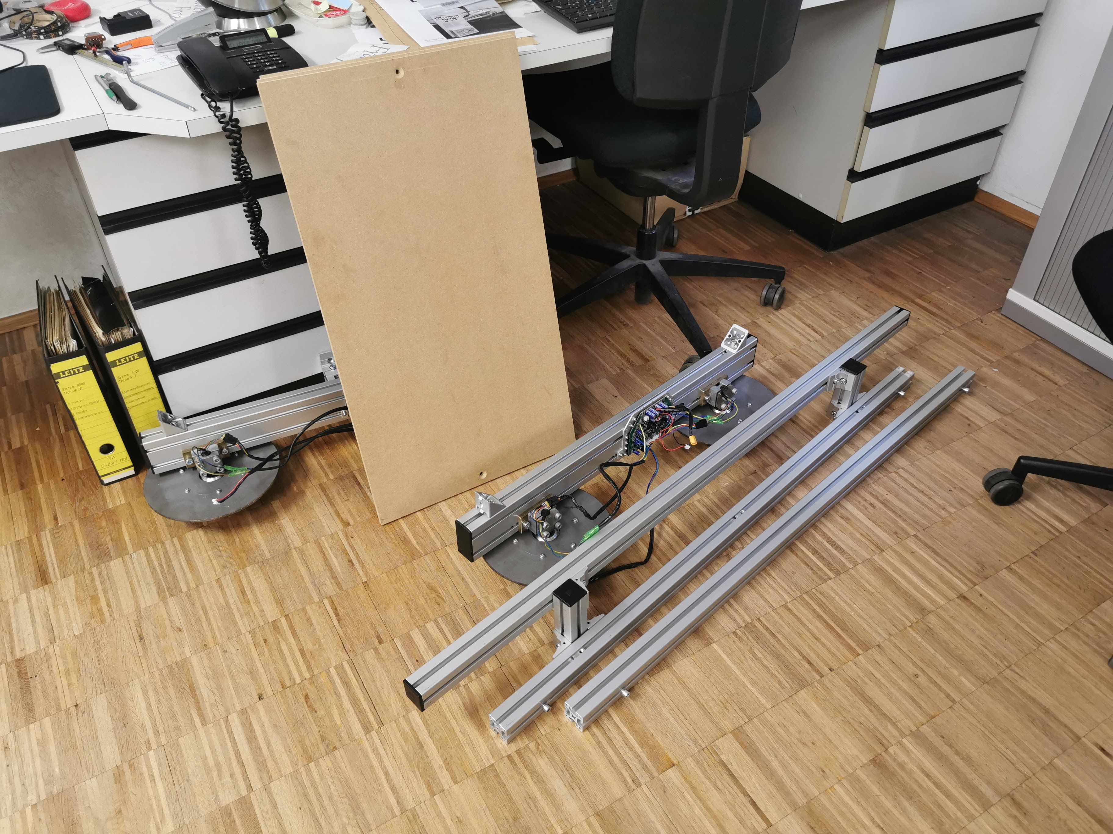
The main part of the build! This is what holds it all together. We started by sawing out the motor mounting brackets from the original hoverboard frames.
After this was done, Phalos removed the burrs and remaining metal, so we had nice and smooth edges.
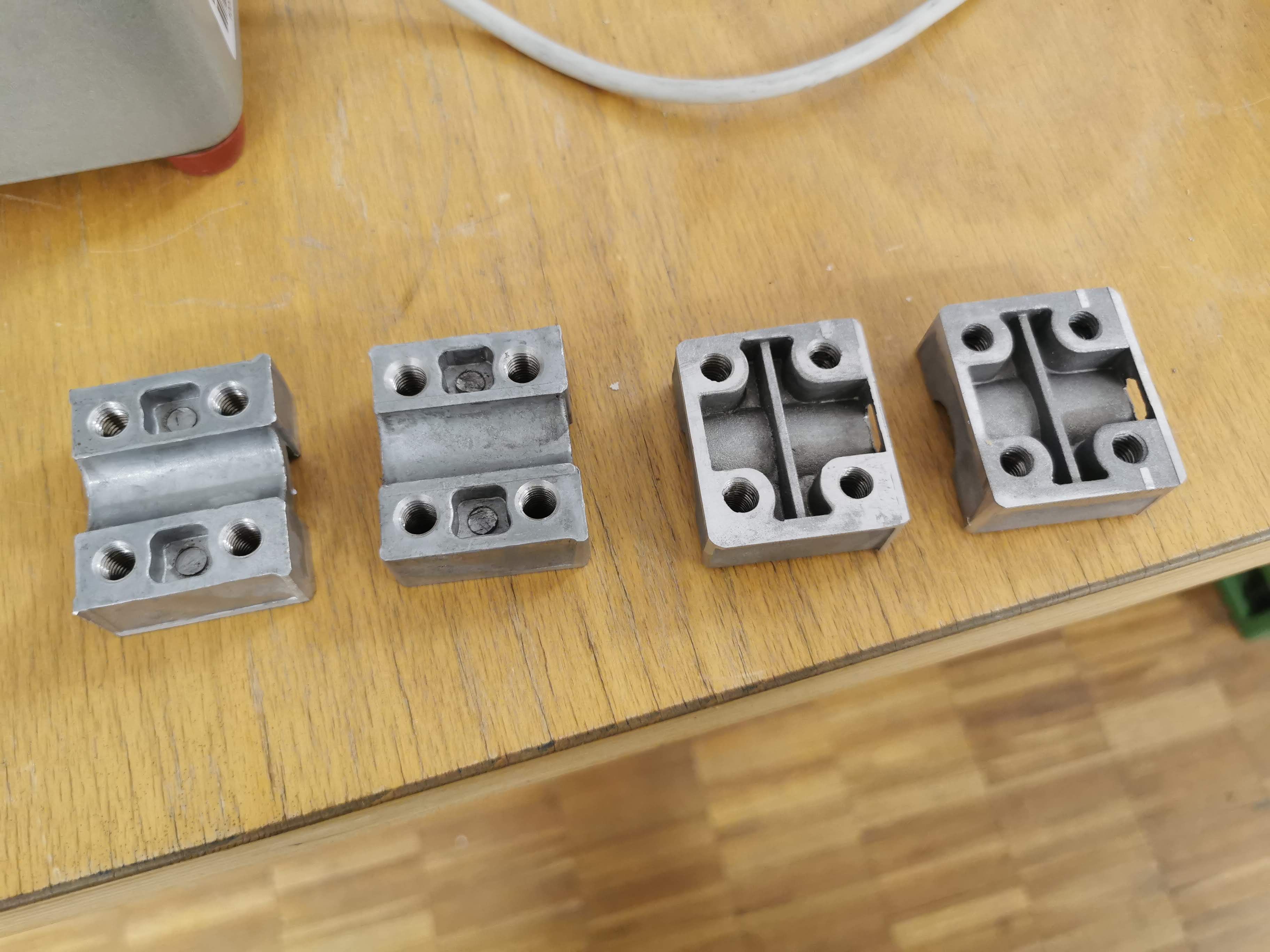
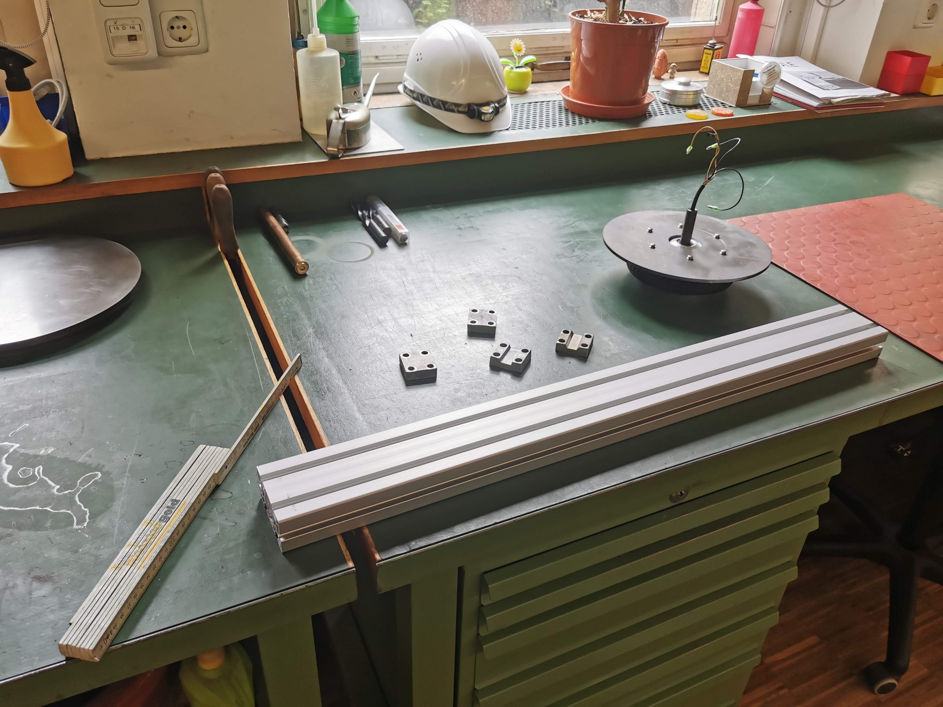
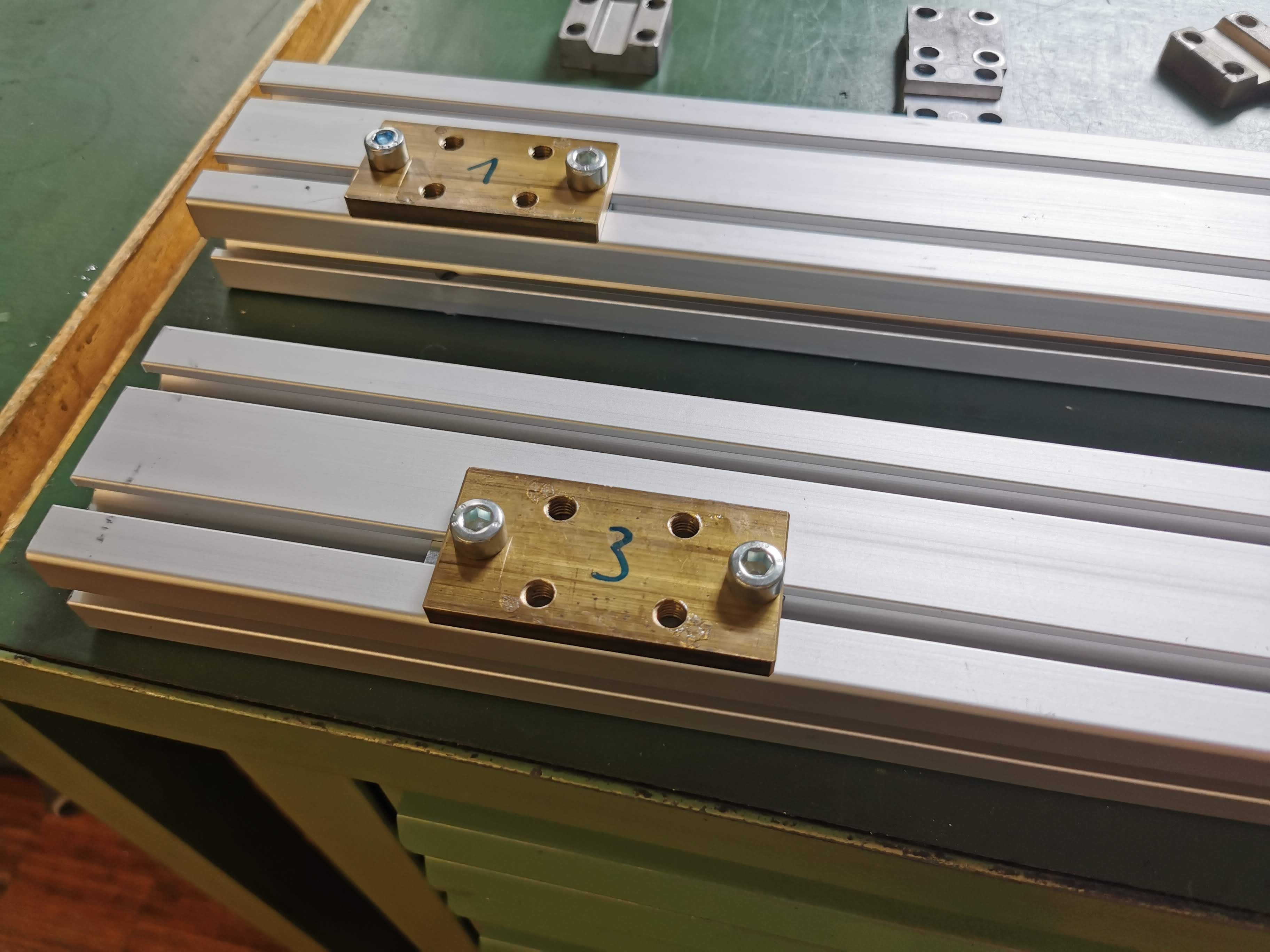
Next, we prepared four small brass plates to adapt the motor mounts to the slotted aluminium extrusion. The goal was to not have to drill into the extrusion at all, mounting everything using the existing slots.
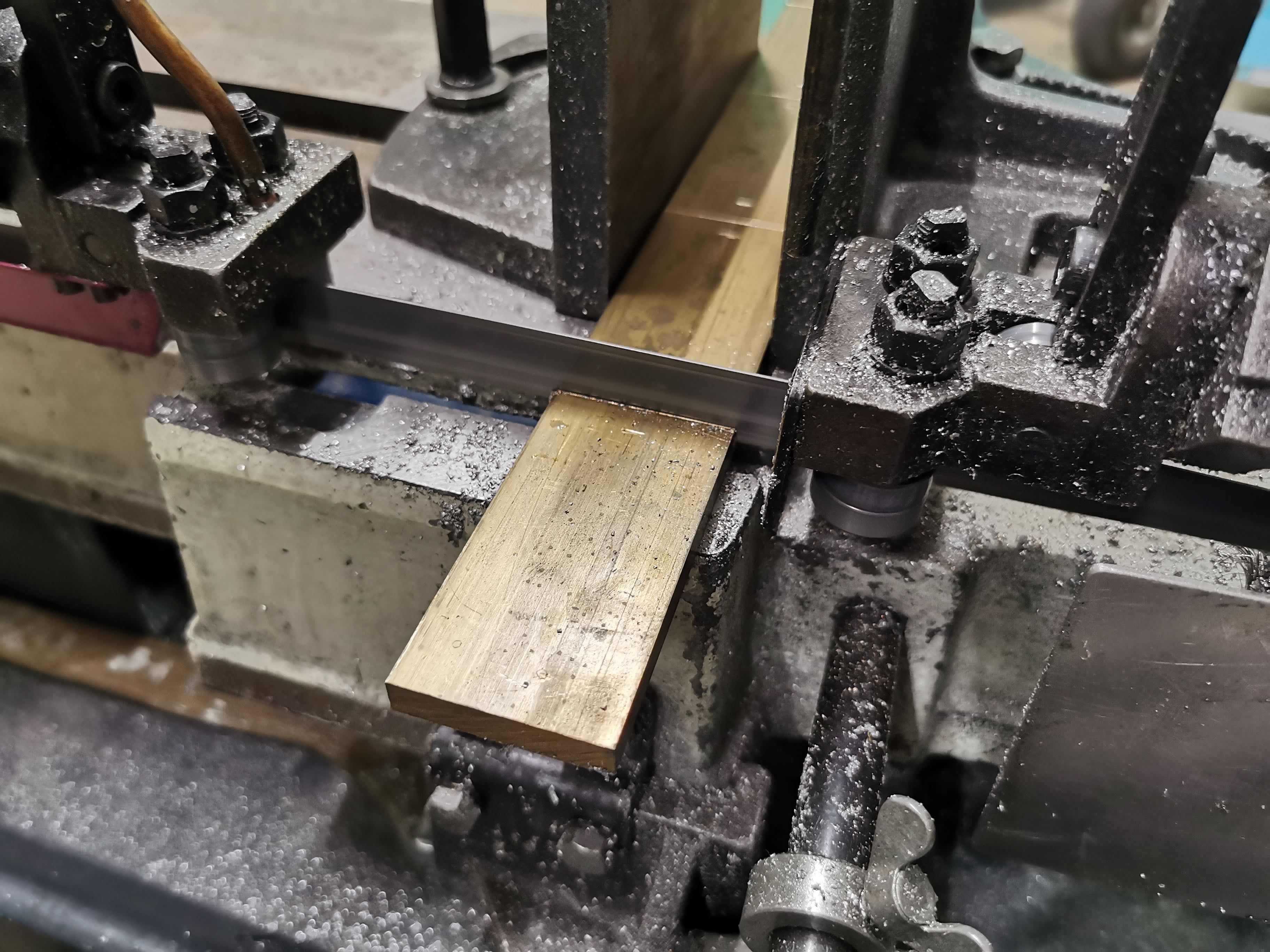
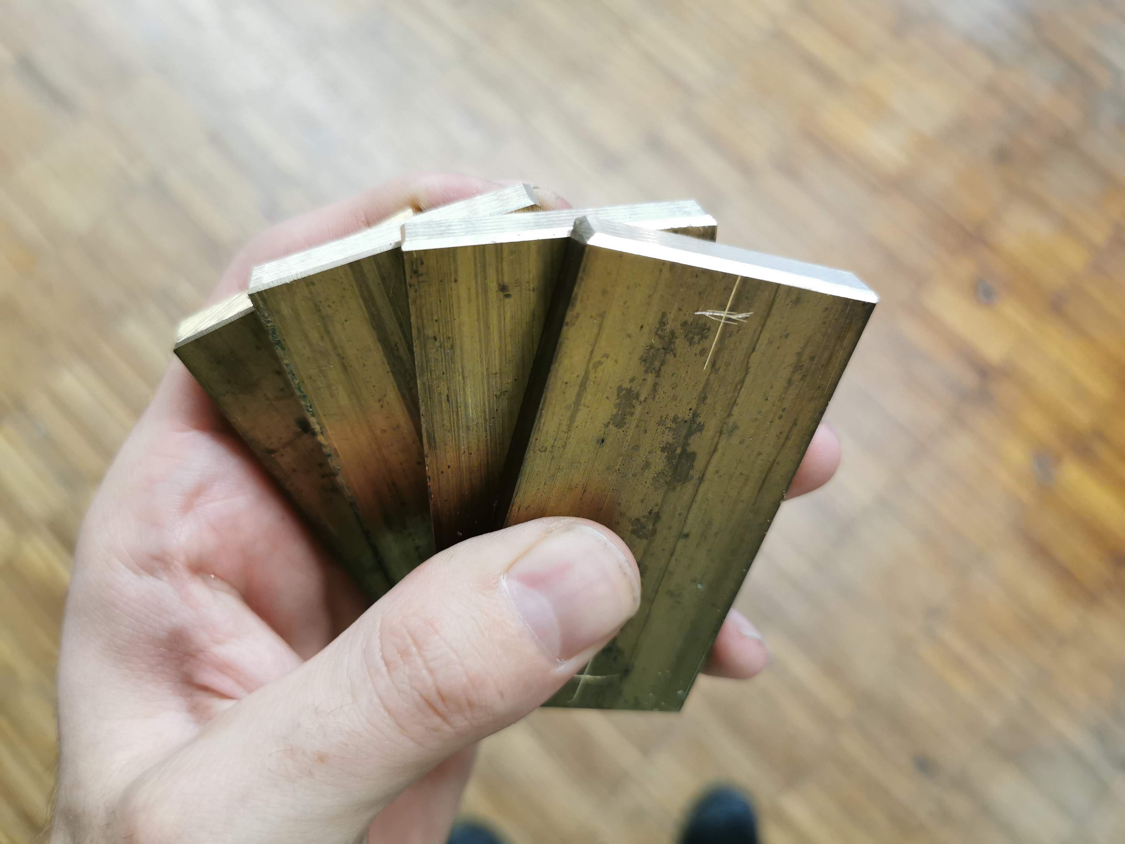
Phalos put the plates through an automated deburrer, a nice tool I did not previously encounter. Afterwards, I marked out where to drill, Phalos drilled the holes and I cut the threads for the motor brackets.
The first motor was mounted and everything fit together really well, as it should! The remaining three motors also were easy to mount. So now it was time to mount the control boards.
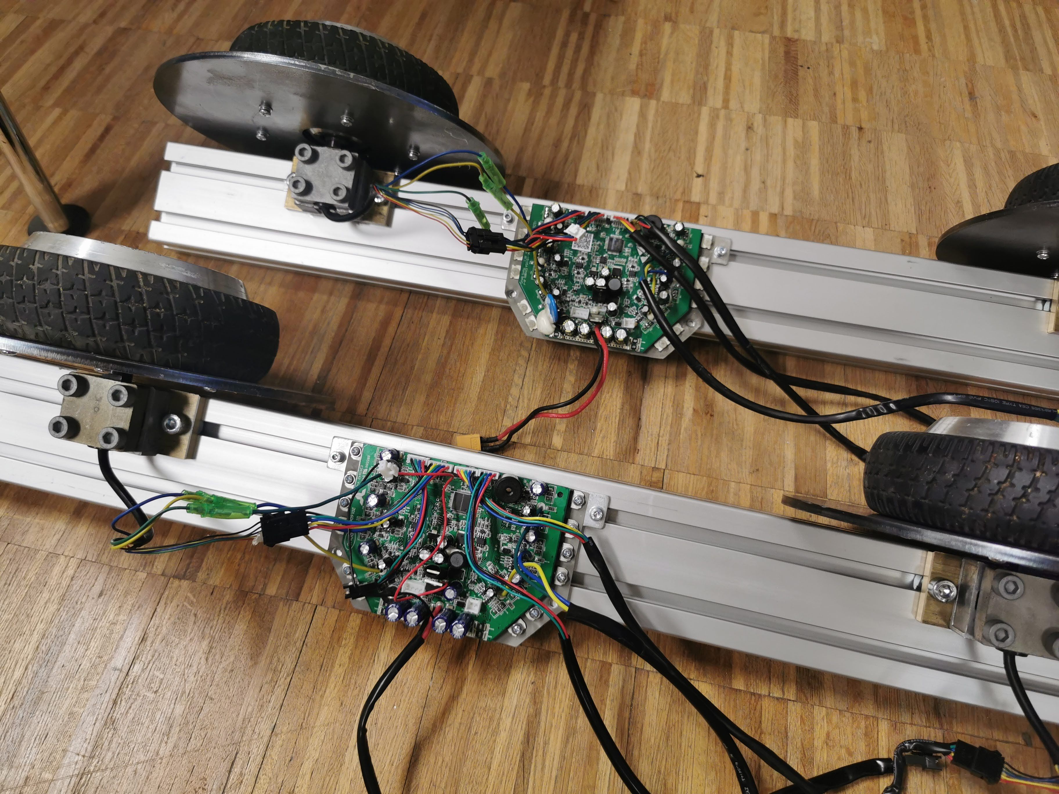
The electronics are the mainboards from the two gutted hoverboards. There is an excellent alternative firmware out there which I have used for my electric street kart in the past. I simply used two of the existing holes in the baseplate to mount the control boards. After that, it was time to see how it all fits together.

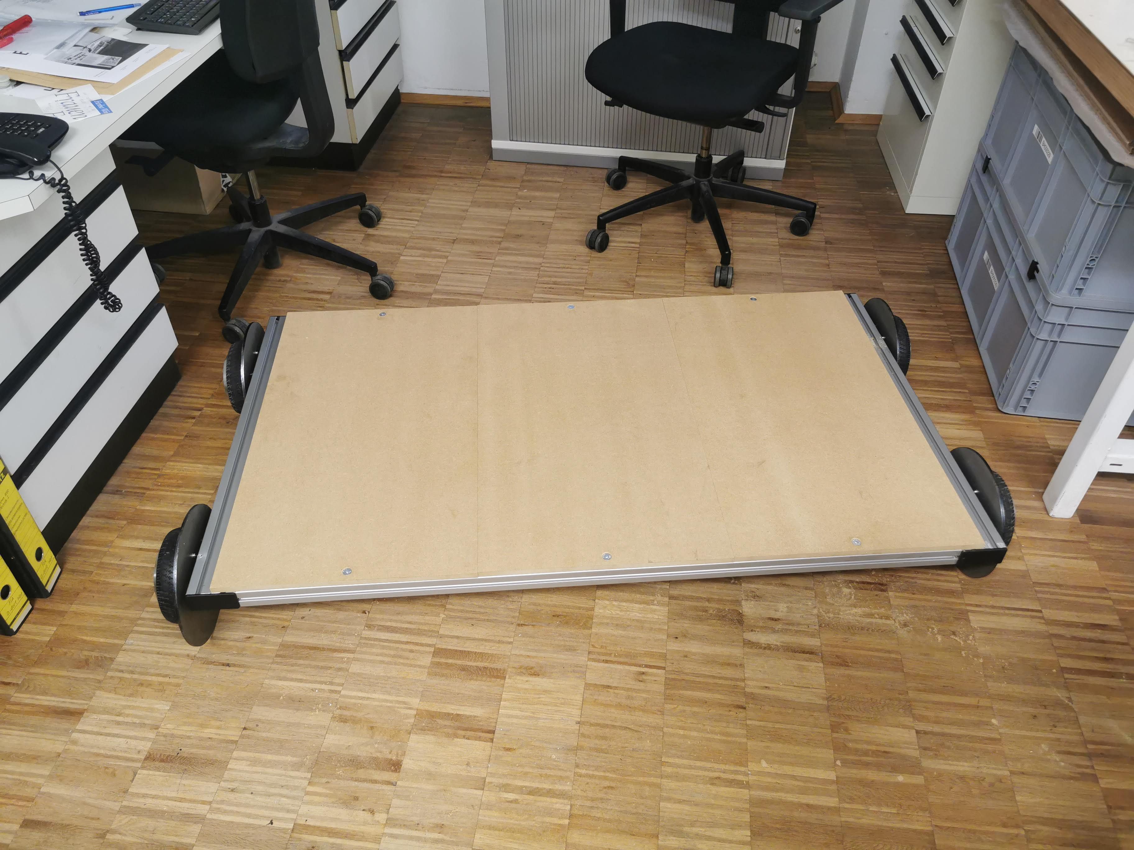
Assembling the frame was easy and a load test with Phalos and me sitting on it showed it to be sufficiently stable, despite the non-optimal direction the angle connectors were being loaded. Disassembling it went even easier and resulted in some nice, compact parts.
A nice frame is good and all, but I want to drive this thing, not just look at it. So there needs to be some way to tell it where to go. Well, actually, that's kind of the job of the rails. But I need to tell it how fast to go and in which direction, anyway!
I wanted it to have one or two single-axis joysticks for throttle and brake. But no matter where I looked, I could not find the kind of joystick I was looking for at the prices I had in mind. All I found were either game controllers, which have two axes, digital "joysticks" which just have switches at the end, not an analog output, or the kind of joystick you would find in an excavator or other heavy industrial vehicle, and those cost some serious money. So I decided to build my own joystick.
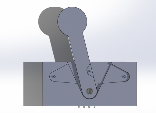
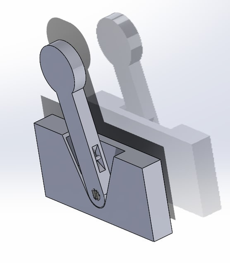
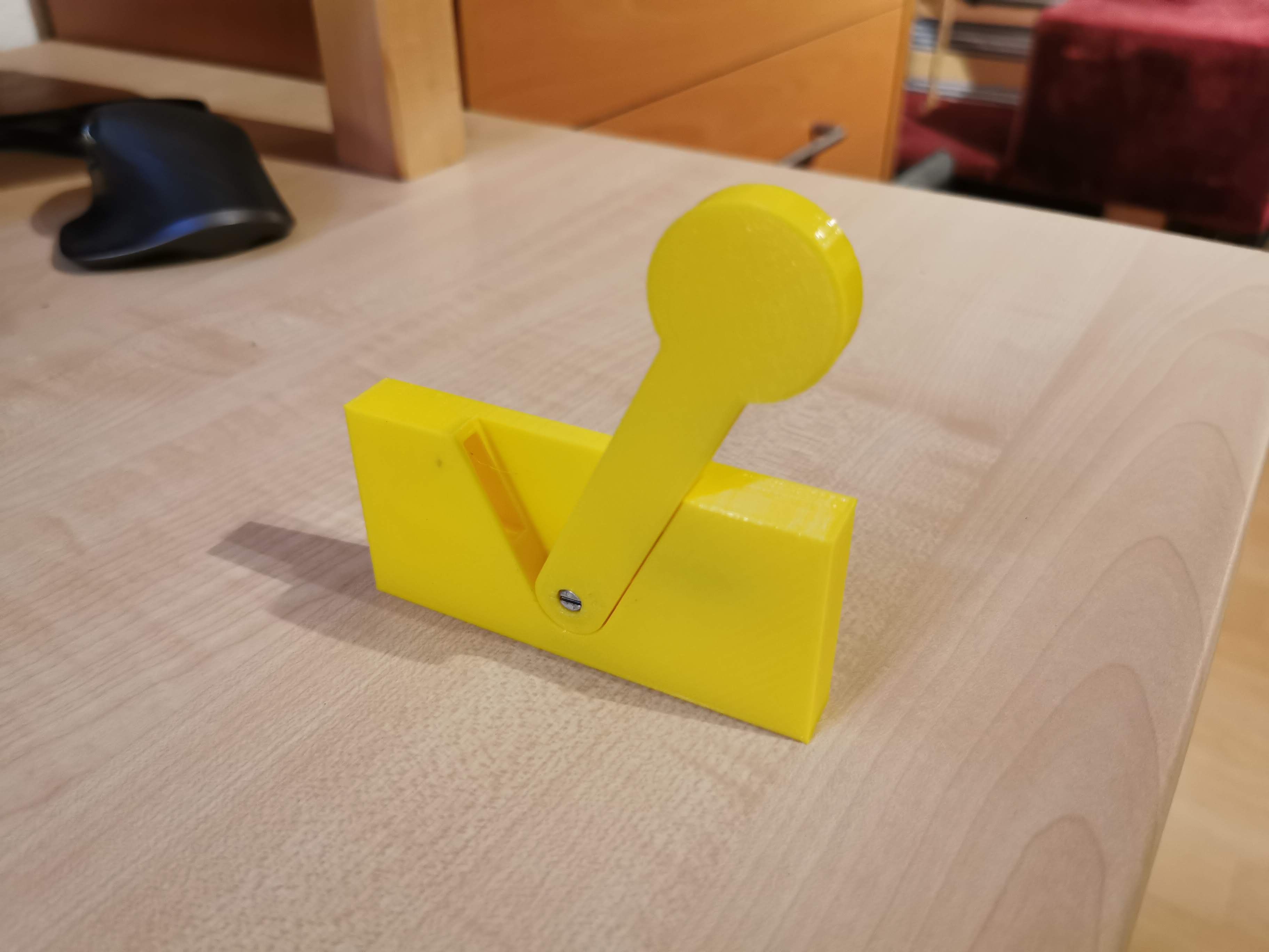
I went for a basic, easy to print flat design, with a potentiometer acting as the fulcrum for the lever. Not seen in the picture is the spring which is embedded into the casing and pulls the lever back to its default position. After getting satisfying results with the first version, I made it a bit more compact, put the spring a bit closer to the fulcrum to make it a bit weaker, and added mounting holes.
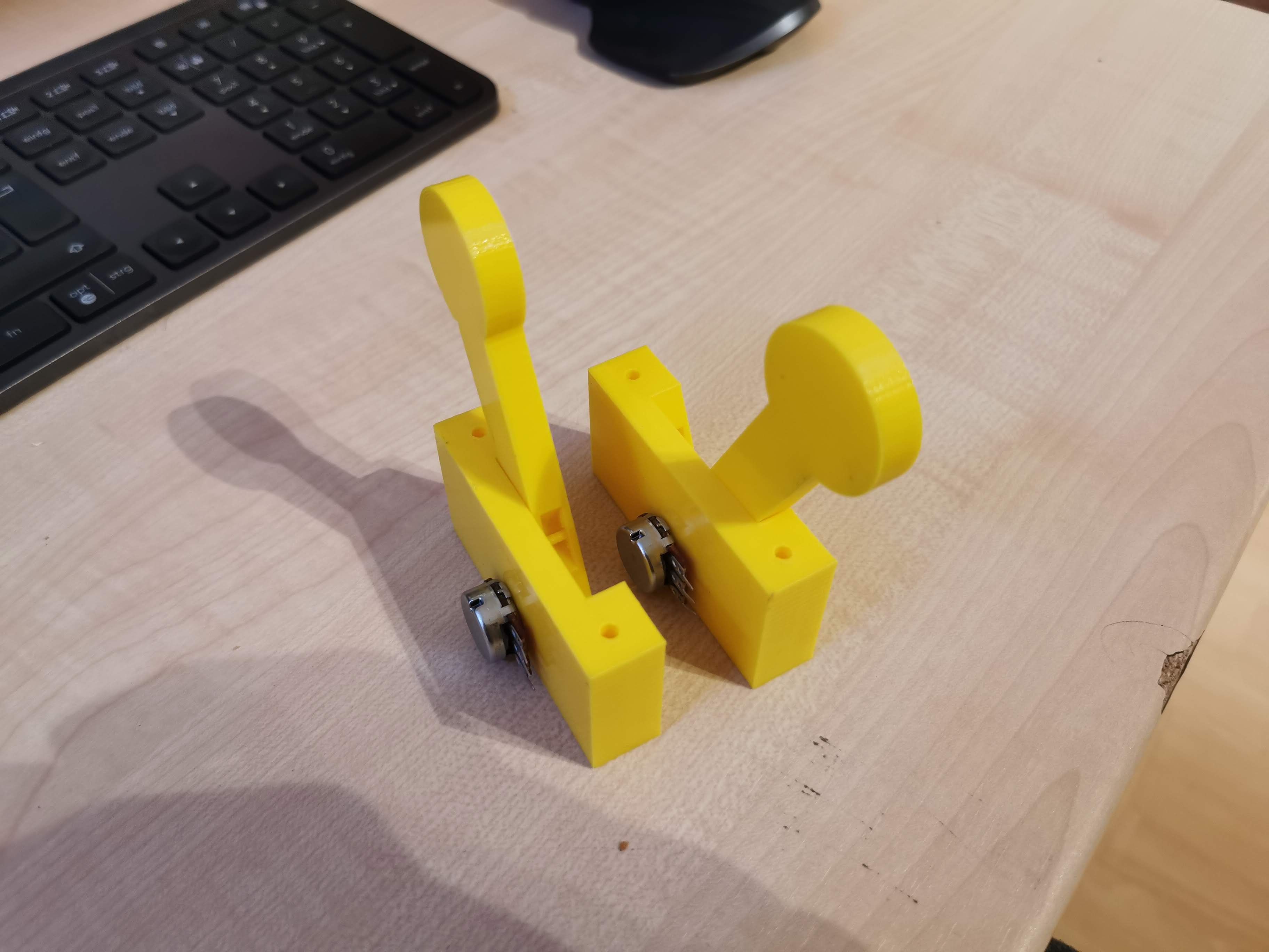
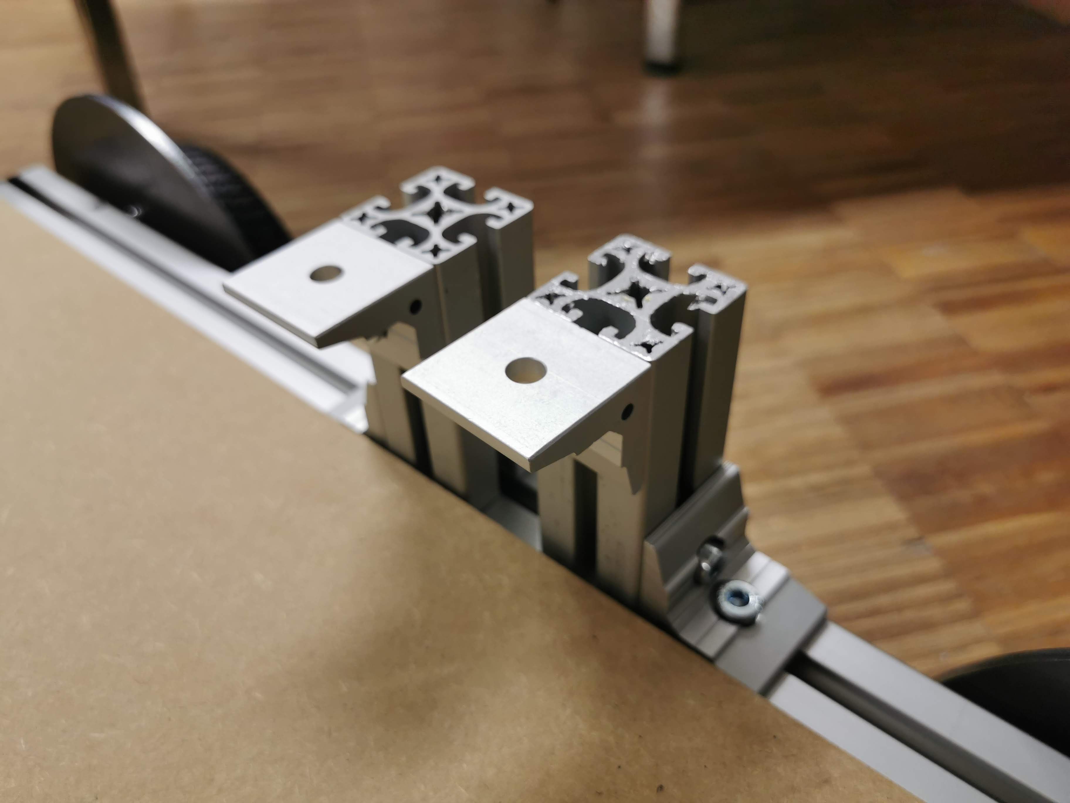
I made one joystick go up and one go down by default, so I could use one for throttle and one for brake / reverse (which also allows me to have the same arrangement of joysticks when driving backwards). I had already prepared two small posts of aluminium extrusion when we built the frame, so I could mount the two joysticks there with some sort of adapter plate I had yet to design. Until then, I focused on making an enclosure for the motor control boards and making the whole thing easier to carry.
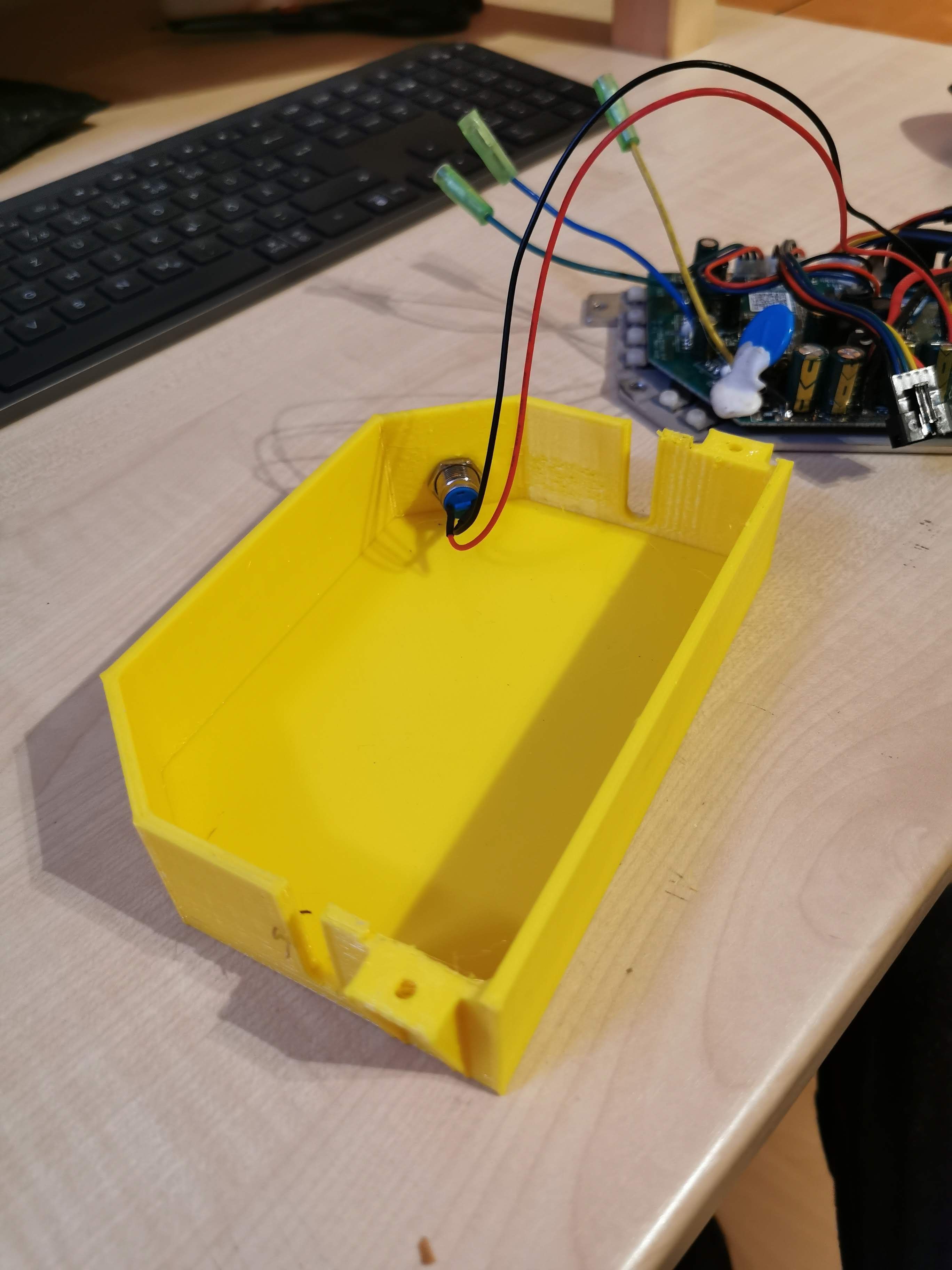

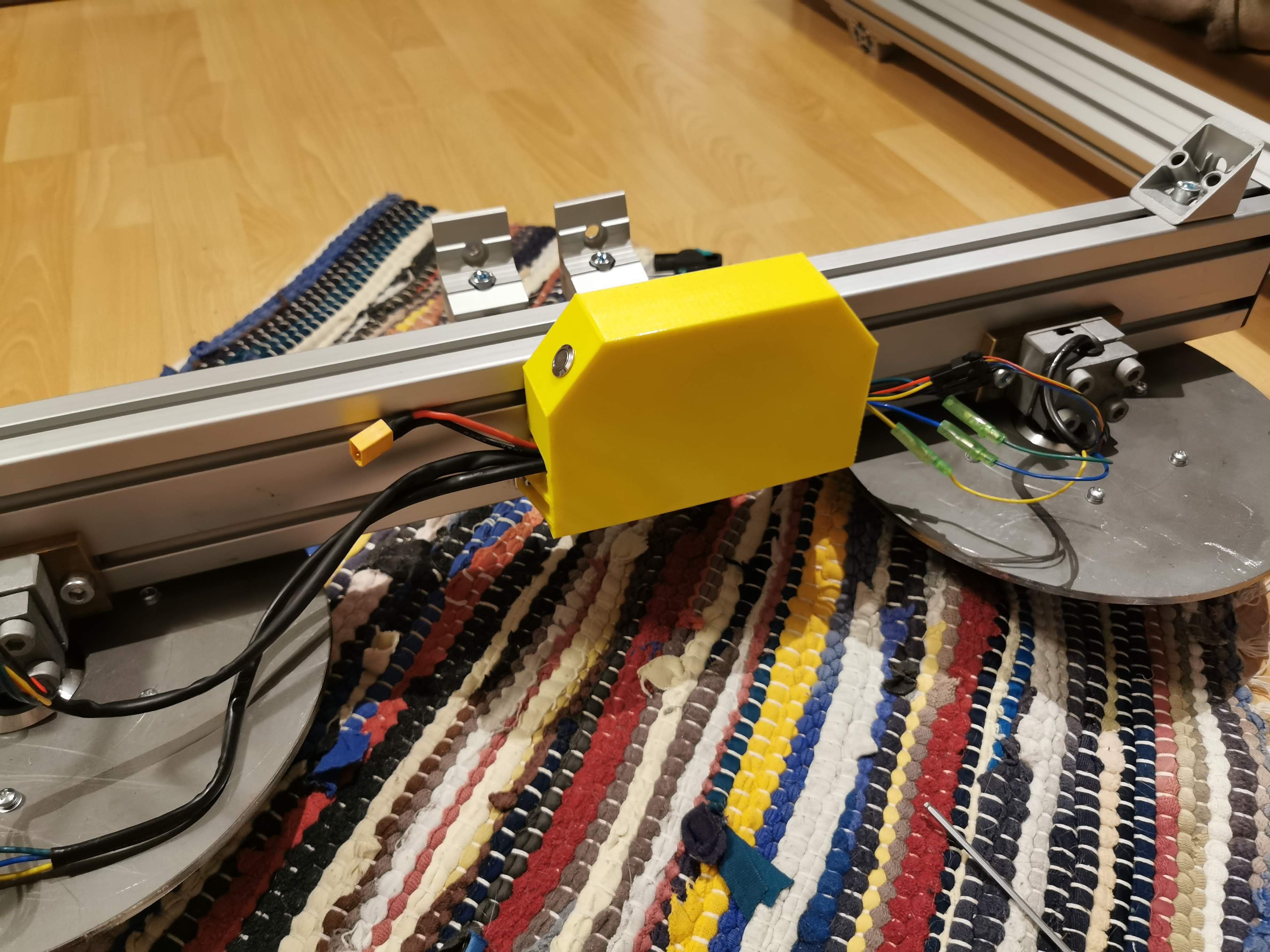
I simply reused the enclosure I had designed for my street kart, but moved the cutouts for the cables around a bit. I also added a hole for the power button, because there is really no need to bring those buttons out to the control module.
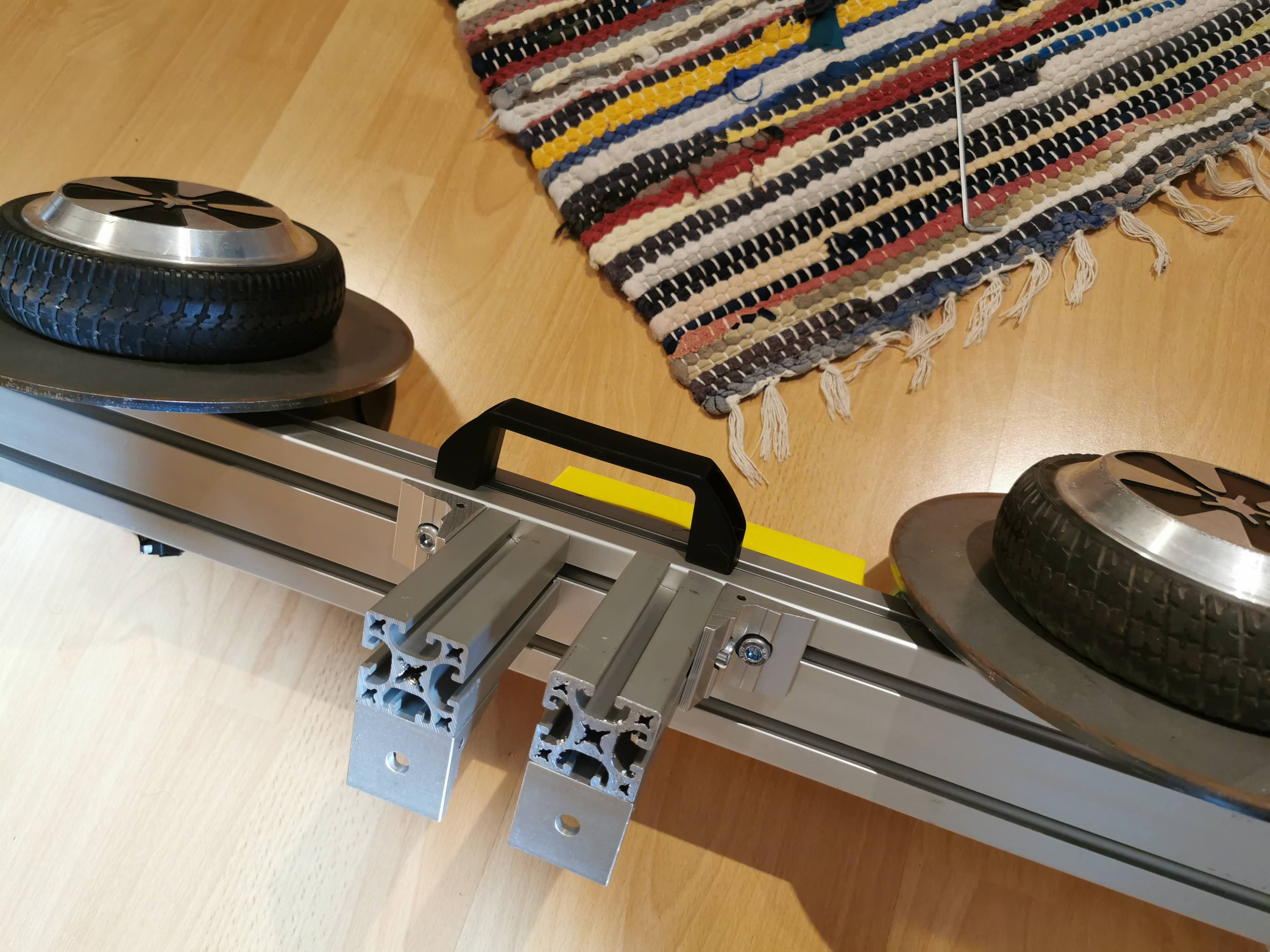
I ordered some simple handles and mounted them to the sides of the extrusions, which made them a lot easier to carry, and also makes the entire kart easy to carry with two people. Indicentally, the angle the extrusions assume when carried by the handle is very close to the one they have when resting on the ground, which prevents surprising rotation when picking them up. Nice! Now back to the controls.
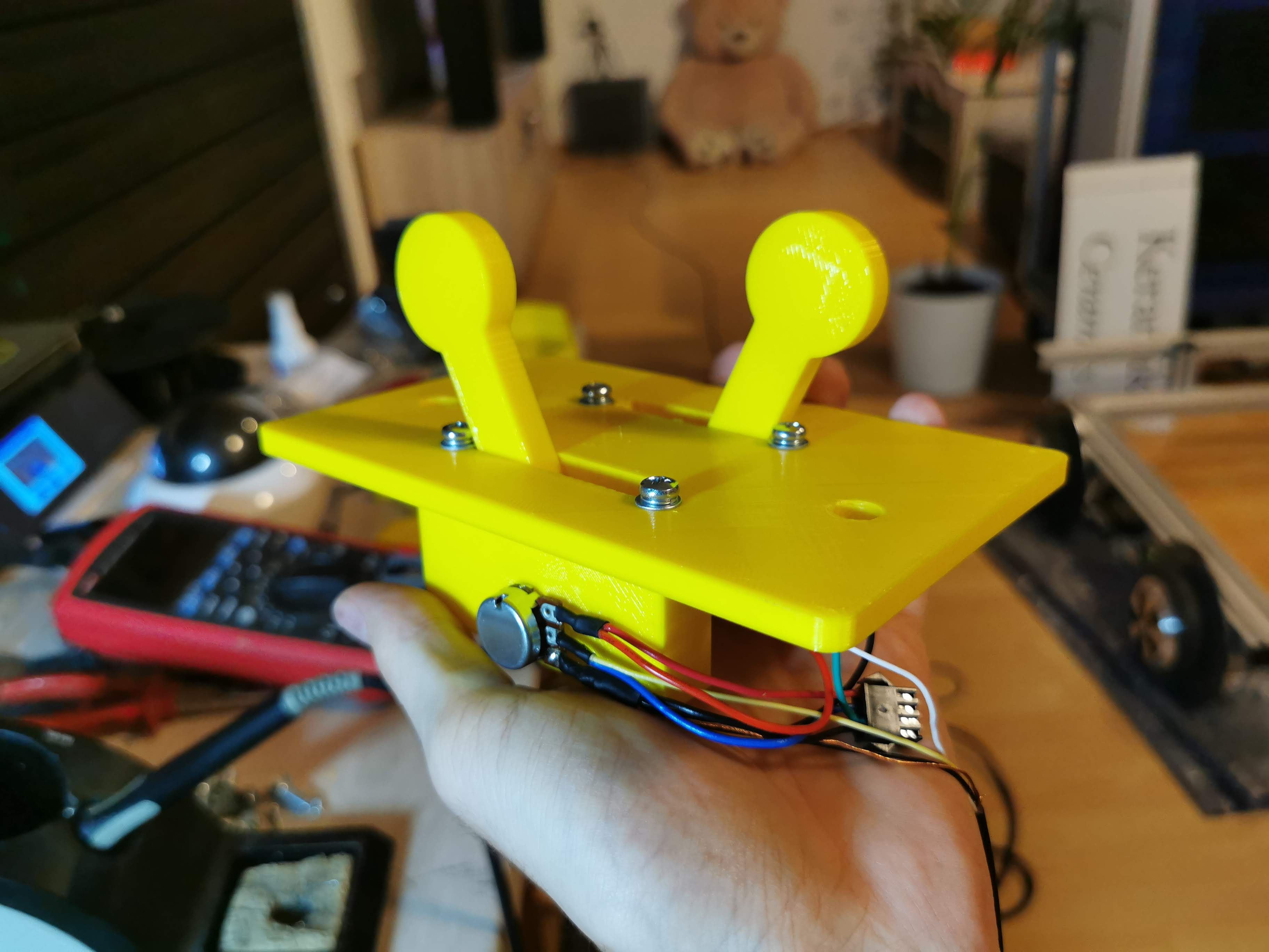
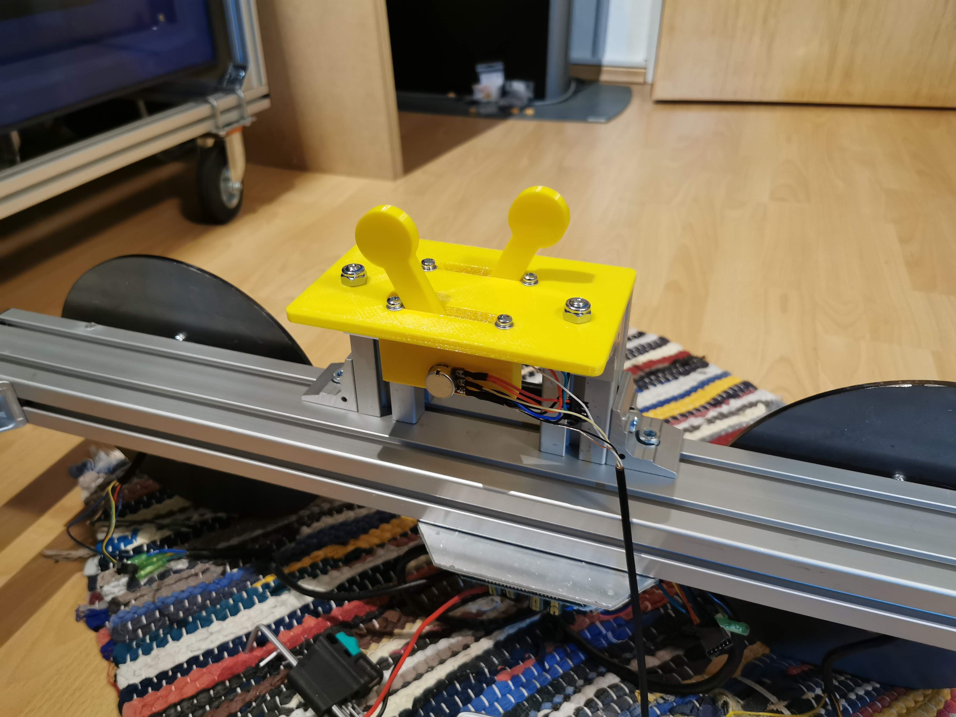
I designed an adapter plate that would simply fit the joysticks and be mounted with two screws onto the prepared extrusions. It should be noted that my first approach was to simply feed the analog values from both joysticks to the two control boards for the left and right motors. Unfortunately, it just didn't work very well, as the signal was very weak (using only a fraction of the rotation range of the potentiometer) and it probably picked up a lot of noise on its way to the left control board, so the wiring you see here is not the final wiring.
I spent an entire evening making the wiring harness to connect the right side of the kart to the left side. Power and data has to go from the right side (where the batteries and control module are) to the left side. Since the kart whould be easy and quick to disassemble, I obviously needed to make that wiring easy to detach as well.
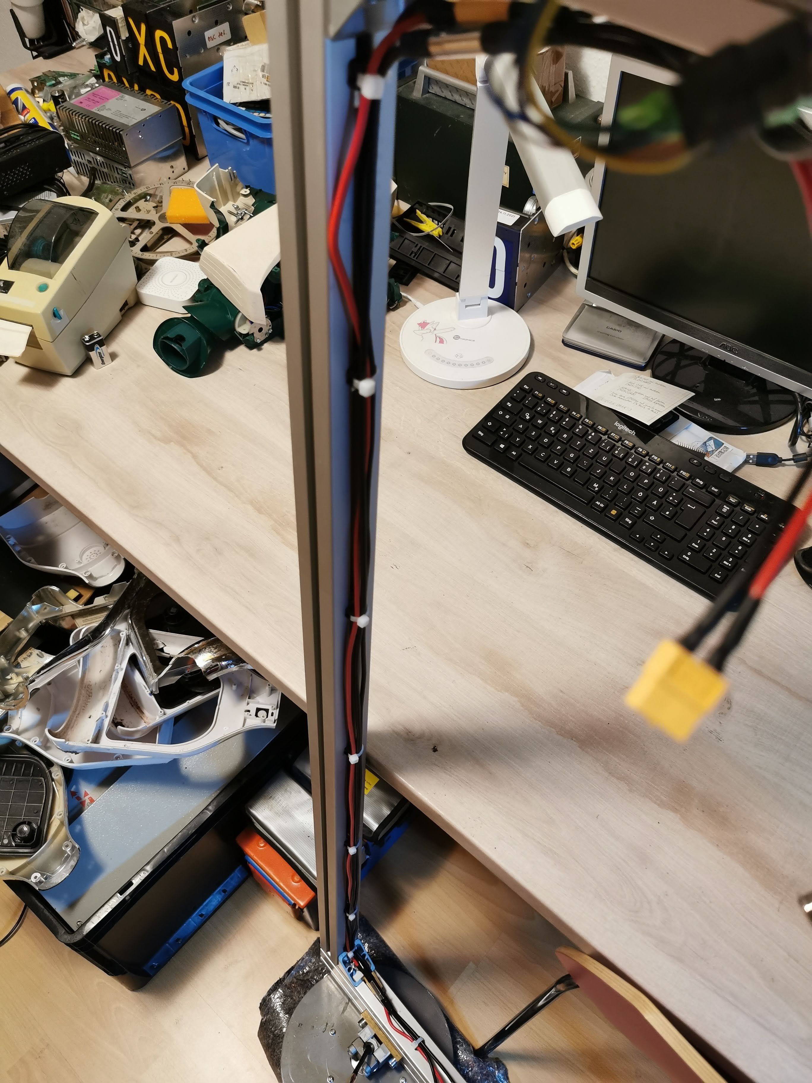
Here you can see the power and data cables on the back lateral extrusion, tied down with cable ties. I used XT60 connectors and 4mm² wire for power and 4-pin Mini-XLR connectors with shielded 4-core cable for the control signals, with the shield tied to ground on the right side.
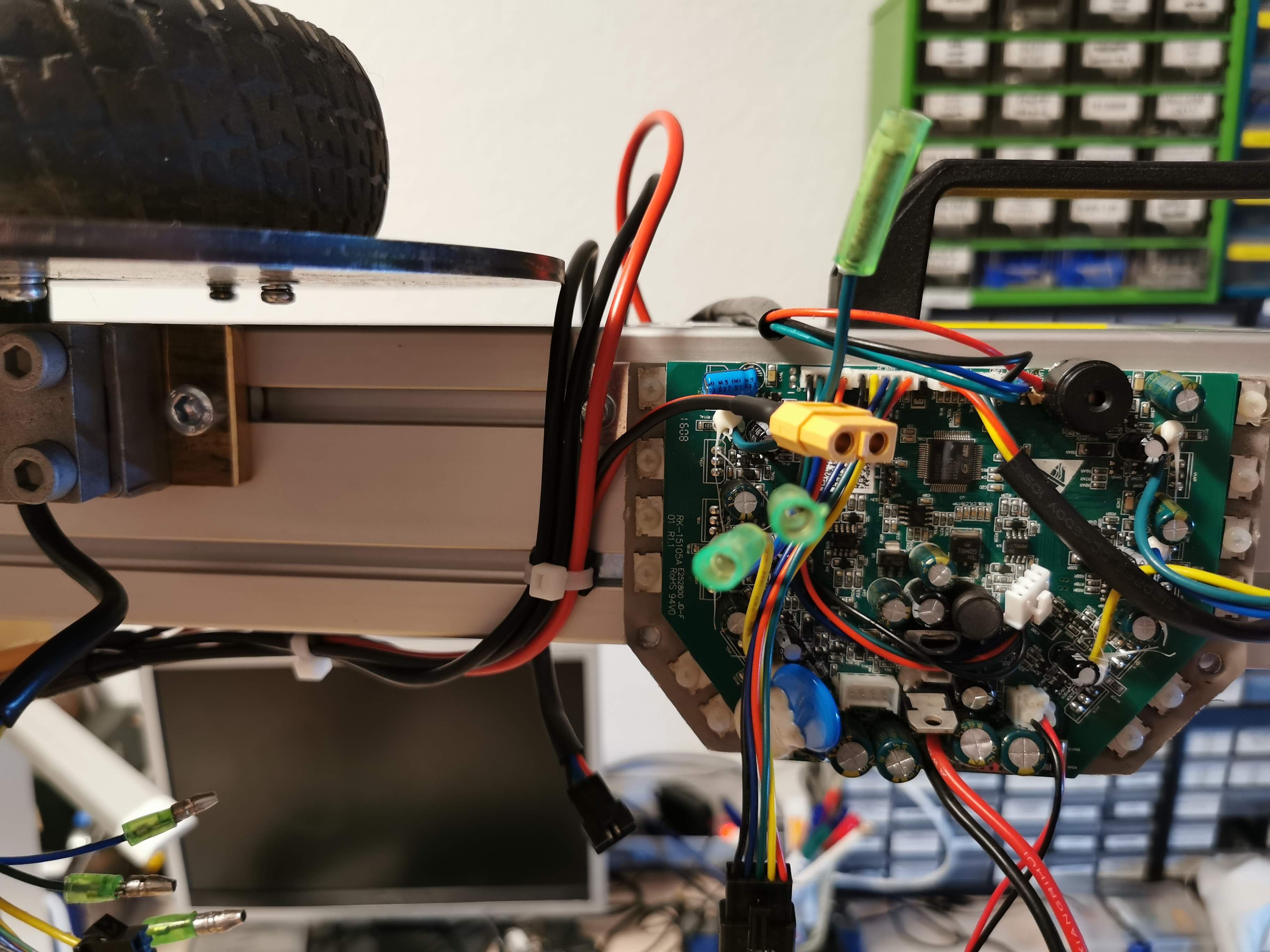
There was just enough space on the right side of the kart to fit the power and data wiring between the wheel flange and the control board. I did later move the board a bit to the right, so it is not actually as tight as you can see in the picture above.
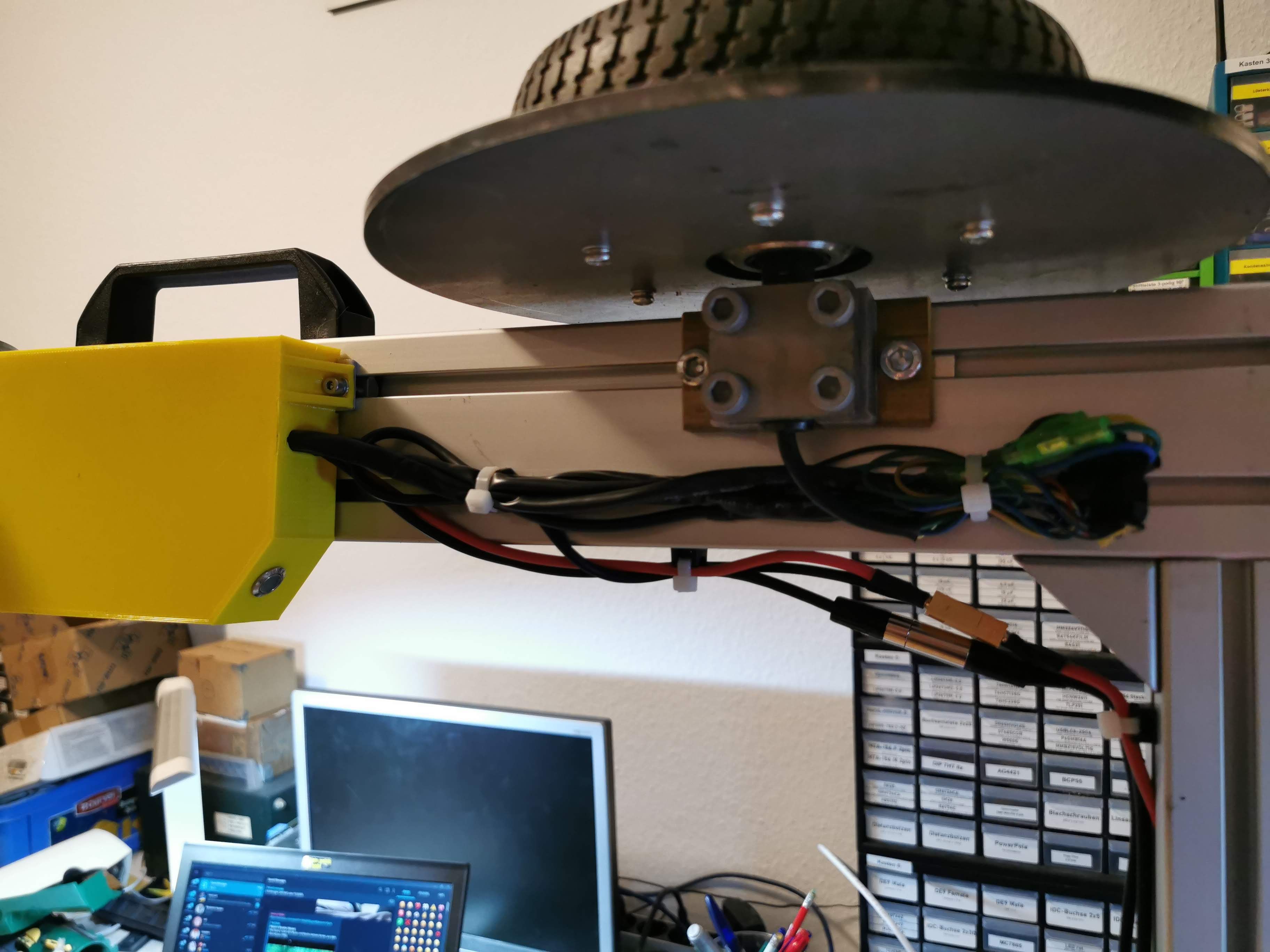
I also tied down the motor wires so they wouldn't catch on any protrusions in the track, like vegetation, sticks or whatever you might find on an abandoned railway track.
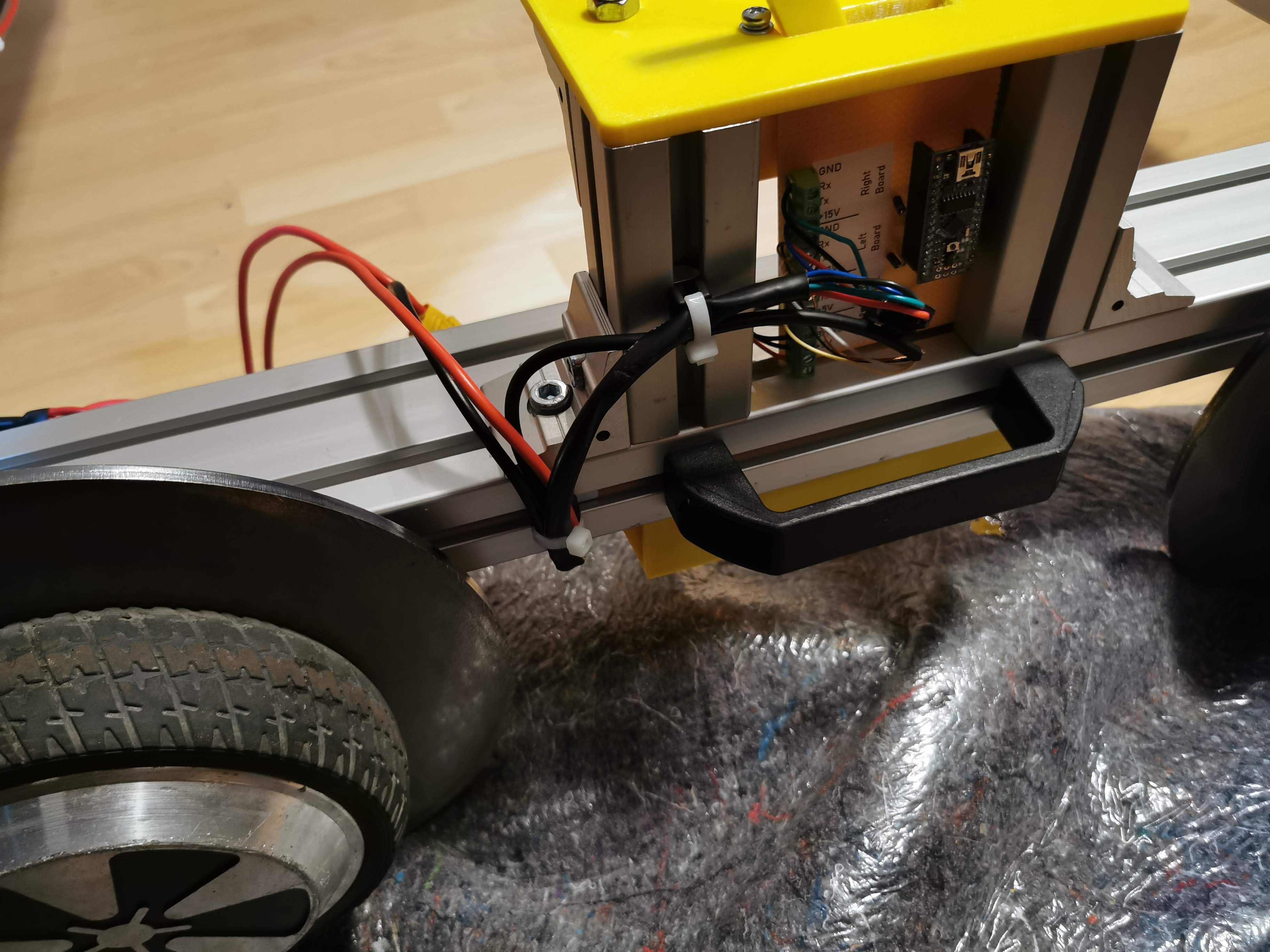
As I said above, the direct analog control didn't really work, so I switched to using an Arduino inside the control module to read the analog signals from the joysticks and map them into a serial data protocol which goes to both motor control boards. This has several advantages:
With all the electronics working, I finally went on to do a first test run.

It worked really well, I was pleasantly surprised that the kart would neither get stuck, deform, jam or otherwise fall apart. It reached a top speed of 21 km/h, which is actually slower than I anticipated based on experiences with my street kart, but more than enough to have fun. One of the biggest fears I had was that the steel wheel flanges would get ground down very quickly, but I can say that this is not the case. They get scratched (obviously), but hold up very well. The ball bearings in the motors also seem to still be in perfect condition, even after absorbing some pretty heavy shocks caused by the (higher than you would find on normal trains) wheel flanges hitting bolts or other obstacles inside the track.
A few days later, I spontaneously decided to test it at night, and crudely fitted a large COB LED to the bumper, complete with a horribly cut piece of acrylic to protect the LED. Because that was a quick and dirty thing, I just wired it up to one of those DPS-something adjustable power supply modules and powered it with a leftover hoverboard battery.


I will keep posting my findings in this separate post, which will be updated as I collect some experience!